High Voltage Cable System Design
Challenge
The project required identifying a bonding method for cable screens that would keep the voltage rise within acceptable limits and ensure the cable could withstand maximum short-circuit fault currents. Initial evaluations showed that common bonding techniques, such as single-point and solid bonding, resulted in screen voltage rises exceeding the specified limit for the site. While these methods were simpler and more cost-effective to implement, they did not meet the technical performance criteria.
Solution
The objective was to recommend a solution that satisfied all relevant cable requirements: managing voltage rise at the screens, specifying adequate cross-sectional area to handle short-circuit currents, and ensuring the cables' current-carrying capacity.
The project began with an ampacity study of two proposed 150 kV circuits using 1600 mm² aluminium conductors and 95 mm² copper screens. The study accounted for installation techniques and environmental conditions to ensure cable temperatures would not exceed 90°C. Simulations were then run to evaluate the induced voltage rise and determine the most effective bonding strategy.
It was found that the 95 mm² screens alone were inadequate for withstanding a 63 kA short-circuit current. As a result, additional Earth Continuity Conductors (ECCs) were proposed. The final configuration combined the use of screens and two ECCs, which proved optimal for the dual-circuit design.
The ampacity analysis was carried out using Cableizer, based on the IEC 60287 method, while ATP EMTP software supported the short-circuit and voltage rise simulations. The assessment was completed in collaboration with the Cable team and reviewed by technical director Jonathan James.
Impact
The outcome confirmed that the recommended cable configuration met all technical requirements, including acceptable voltage rise, short-circuit resilience, and ampacity. This solution not only satisfied the client's needs but also ensured installation feasibility and cost-effectiveness.
Through this process, the team gained deeper insights into earthing path impedance and cable protection strategies under fault conditions. The use of ATP software proved particularly valuable in modelling worst-case scenarios and refining the design accordingly.
Next Steps
Although the initial assessment proceeded smoothly, cable designs often evolve based on client feedback and installation constraints. Adjustments may be necessary in later stages to account for site conditions or specific client preferences.
The team will remain involved as the project moves forward, supporting any refinements needed to ensure the final solution meets performance and reliability goals.
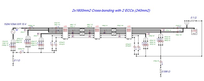
A single-phase-to-ground short circuit was simulated using ATP software
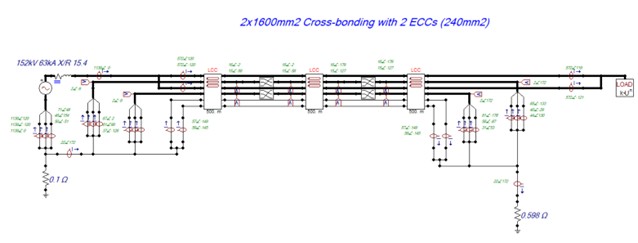
The induced voltage rise under normal operation on the screens was evaluated using ATP software
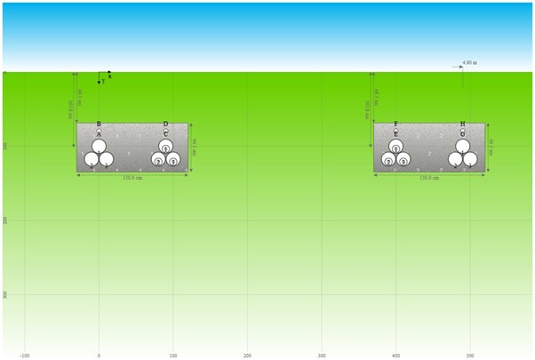
Cable Ampacity was assessed using Cableizer
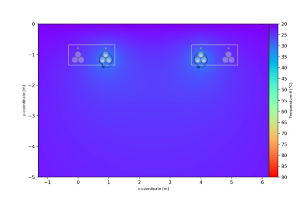
Cable temperature results from the Cableizer.
Temperatures must be below the cable’s maximum operating temperature (90°C).