Fault Infeed Determination
About Fault Infeed
The proliferation of distributed generation installations, means that new connections to distribution networks are often subject to constraints imposed by the design performance of the pre-existing distribution network switchgear. In particular, distribution network operators (DNOs) habitually impose limitations upon the allowable fault infeed contributions from a distributed generation plant.
Such limitations do not pose a problem for most solid state generation installations such as solar farms which contribute inherently very little fault current. However, where energy conversion is undertaken using conventional rotating generation plant, the fault infeed contribution is potentially significant and can becomes a major obstacle to achieving a practical and economic connection.
To mitigate this issue it is necessary to place additional impedance between the network and generation plant to limit the transfer of fault current between them. The fault current limiting effect can be provided by increasing the internal impedance of the synchronous alternators or, if the generation and distribution voltages are different, by increasing the impedance voltage of the step-up transformer. Alternatively, a fault limiting reactor can be introduced if the generation and distribution voltages are the same.
The consequence of introducing additional reactance into the plant is its effect on voltage regulation on the generation plant when it is called to operate over the range of power factor demanded by the DNO at the point of common coupling with the distribution network. In summary, the generator and auxiliary terminal voltages can vary considerably (and potentially unacceptably) over the operational range required of the plant.
Customer Challenge
An EPC contractor and main equipment supplier of gas engine driven generators required an electrical system design to meet the particular requirements of a connection offer. The design needed to fully comply with the fault infeed limitations and operational power factor capabilities defined in the offer whilst maintaining acceptable voltage levels on the plant. The cost to achieve this performance needed to be identified and included within the EPC contractor’s tender offer for the plant.
PSE2 Solution
The DNO connection was at 33kV, the generation voltage was at 11kV, and the design of the alternator was fixed due to contractual conditions with the machine supplier. The objective was therefore to select an appropriate step up transformer - defining rating, impedance voltage, winding voltage levels, winding tap range and intervals - to provide adequate limitation of the fault infeed contribution whilst maintaining acceptable voltage levels within the plant.
Example: 35MVA Transformer with On-Load Tap Changer
The DNO fault infeed for this project was extremely limited. The Owner intention was to export 20MW of power onto the DNO network for phase 1 and then add an additional 15MW. This would be achieved with an initial set of 10 x 2.5MVA gas engines and later with an additional 5 x 2.5MVA gas engines.
The connection offer indicated an infeed limit of 1.05kA (60MVA at 33kV). As a rule of thumb, if the fault infeed constraint is less than 2.5 x the MVA rating of generation, the offer is impractical with synchronous machines. Whereas it would be possible to limit the fault infeed for a 20MW plant, it becomes impractical for a 30MW plant.
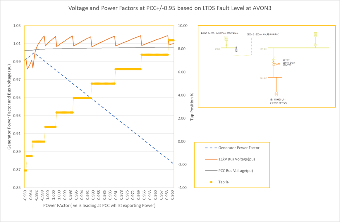
The DNO indicated that the infeed figure was a reflection of the original application and that greater headroom could be available. The outcome in the above figure represents a 35MVA 33/11kV transformer with an impedance voltage of 22% on rating. At full load this transformer will have a reactive leakage of around 7.7MVAr (22% x 35MVA). 30MW of export power would require an import of 9.8MVAr to operate at a 0,95 leading power factor. The higher impedance of the transformer limits the fault current but also helps to provide a reactive load to allow the generators to operate near unity and not too far leading (0.99 in this case for an 0.95 leading power factor at the PCC) with a low internal voltage near their stability limit.
To meet the full range of power factors an on-load tap changer was required. This was provided over the range of +/-10% with a tap step of 1.25%. The tap changer permits regulation of the 11kV voltage for the full range of power factors as is illustrated in the above figure.
Further analysis is now required to determine if the transformer can energise within the 10% voltage step allowance for an abnormal event with a maximum inrush condition and if not, to consider mitigation methods.
Find out more about our Power System Analysis services and Electrical System Design.